
Loop Delta User Guide
User Guide
Introduction
Loop Delta is an accurate and reliable solution for differential pressure measurement. The device is designed specifically for monitoring HVAC and ventilation systems in locations where wired measurement is not possible or practical.
Loop Delta measures differential pressure, temperature, relative and absolute humidity, dew point temperature, and device movement. The device’s intelligent filtering eliminates momentary disturbances such as wind gusts and door openings, ensuring that measurement results reliably represent the actual pressure difference.
Typical applications include:
- Filter pressure drop monitoring
- Room-to-room pressure difference monitoring (e.g., clean rooms, isolation rooms)
- Ventilation duct pressure measurements
- Building pressure relationship monitoring
The device operates autonomously and the only maintenance required is battery charging, which needs to be done approximately every 12–24 months depending on device configuration and radio conditions. The device can be configured remotely via the Loopshore cloud service. Contact us for more information.
The device communicates with the cloud service via a secure and encrypted data channel using 4G/5G networks.
Safety
| Topic | Information |
|---|---|
| Usage | Recommended operating conditions: -20°C to +40°C, 0–100%RH. For indoor use. Outdoors, the device must be protected from rain, see Outdoor Installation. |
| Battery | The device can be used battery-powered or connected to a USB charger. The device can operate for up to 24 months on a single charge. |
| Full battery charging takes approximately 8 hours under normal indoor conditions. | |
| Charge only with a compatible USB-C charger. | |
| Battery does not charge below 0°C. Charging is up to 10x slower at 0–10°C. | |
| Capacity decreases in the cold: at -10°C the battery provides approximately 70% of its rated capacity. | |
| Enclosure | IP class 20. >12.5mm objects. No liquid protection. Outdoors, the device must be protected from rain and snow. |
| In case of problems | Turn off the device. Contact the manufacturer. |
| Manufacturer contact information | info@loopshore.com, loopshore.com |
| CE declaration of conformity | Loopshore Oy declares that Loop Delta complies with directive 2014/53/EU on radio equipment. A complete declaration of conformity can be ordered by contacting info@loopshore.com. |
Package Contents
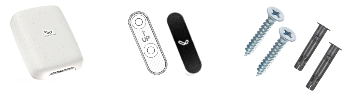
| Item | Description |
|---|---|
| Loop Delta | The device |
| Magnetic wall mount and cover sticker | For wall installation |
| Screws and plugs | For mounting |
| Pressure tubing | For differential pressure measurement |
Installation
Warnings
- Install indoors, or outdoors protected from rain. The device’s own enclosure is IP 20 and is not waterproof.
- Do not drop.
- Do not install the device upside down. The device can be mounted vertically on a wall or placed horizontally on a flat surface with the back facing down.
- If the device has been at a significantly different temperature than the installation location, let it settle in the new conditions for one hour before turning on the power.
Placement
Position the device as close as possible to the measurement point to keep the pressure tubing short. Short tubing improves measurement accuracy and speeds up response.
Avoid installing in locations where the device is exposed to direct airflow or mechanical vibration.
Pressure Tubing Connection
Loop Delta has two pressure ports for differential pressure measurement:
- P+: Measures the pressure in the space where the device is located (no tubing required)
- P-: Connect via tubing to the reference pressure (e.g., outdoor air, corridor, duct)
The pressure difference is calculated using the formula: ΔP = P+ − P−
Interpreting results:
- Positive value: The device location has overpressure relative to the reference point
- Negative value: The device location has underpressure relative to the reference point
Example: The device is in a room and the tubing is routed from the P- port to the outdoor air. If the room has underpressure (typical situation), you will see a negative reading.
Tip: If you want to see the result the other way around (e.g., underpressure as positive), swap the tubing connection.
Ensure that the tubing is securely attached to the connectors and that there are no kinks or blockages in the tubing.
See detailed installation instructions in the separate Differential Pressure Sensor Installation Guide, which includes instructions for tubing pass-through, sealing, and capillary tube use.
Mounting
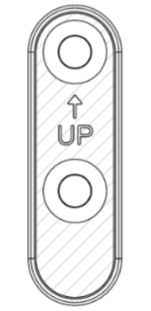
Attach the wall mount to the wall with the screws included in the package. Use plugs if necessary. Finalize the installation with the cover sticker.
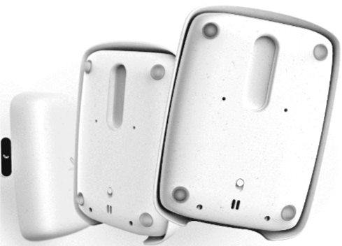
- Connect the pressure tubing to the device before mounting.
- Turn on the device using the switch on the back.
- You will hear a beep indicating that the device is operational and measuring.
- Place the device on the magnetic wall mount.
Tip: You can also attach the wall mount using picture hanging strips (e.g. 3M Command strips, 12–20 mm wide) instead of screws. This requires no drilling and leaves no marks on the wall if the mount is later removed.
Flat Surface Installation
Alternatively, the device can be placed on a flat surface, e.g., on a shelf or HVAC equipment room surface. Ensure that the device is on a stable base and that the pressure tubing does not pull on the connectors.
Outdoor Installation
Loop Delta can also be installed outdoors when the device is protected from rain. The limits of the measurements come from the operating ranges stated by the sensor manufacturers, see Table 1b.
Protection: The device’s own enclosure is IP20 and is not waterproof. Outdoors, the device must be protected from rain and snow, including driving rain, as well as from splashing water and snow accumulating on the device. The protection must not prevent air exchange. The device measures the surrounding air, so air must be able to flow freely around the device. In a closed enclosure the device measures the air inside the enclosure rather than the outdoor air, and moisture can build up inside the enclosure.
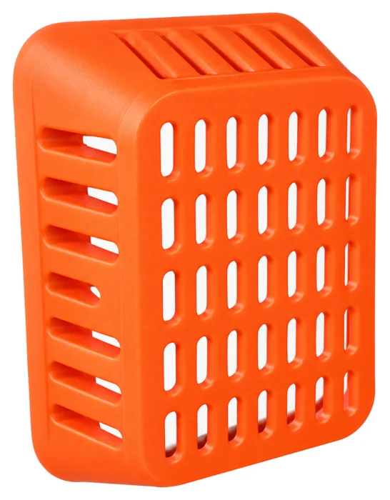
Protective cage is a 3D-printed, screw-fastened grille that protects the device from impacts and prevents it from being removed without tools. It is suitable for sites where the device is exposed to knocks, vandalism or theft.
When installing outdoors, note:
- Temperature: The device operates at -20°C to +40°C.
- Differential pressure measurement: The air passing through the differential pressure sensor must not condense. Water condensed in the tubing can freeze in sub-zero temperatures and block the tubing, so install the tubing with a gentle downward slope towards the outdoor air (see the Differential Pressure Sensor Installation Guide).
- Condensation: When the temperature drops quickly or the air is close to saturation, moisture can condense inside the device. Condensed moisture can distort measurements and damage the device.
- Sunlight: Direct sunlight heats the device and its protection, so the temperature and humidity readings do not reflect the outdoor air. Install the device in a shaded location.
- Battery: The battery does not charge below 0°C, not even when connected to a USB charger. Capacity decreases in the cold (approximately 70% of rated capacity at -10°C), so the charging interval becomes shorter.
Outdoor installation and protecting the device are the user’s responsibility. Damage caused by liquid or moisture is not covered by the warranty.
About Device Operation
The device operates autonomously and normally does not require any adjustments. The following chapters describe the device’s default behavior and some configuration options.
Measurement General Information
The device’s default measurement interval is 5 minutes, and this can be adjusted remotely to anything between 10s and 24h. Note that additional data charges may apply if the measurement interval is less than 10 minutes.
Additionally, device sensors can be calibrated remotely, measurements can be enabled/disabled per quantity, and the device has a GPS that can be enabled.
The device saves measurements to internal memory if it is moved outside of cellular network coverage. When the device has network connectivity again, it will send the measurements to the cloud service. Note that the device must not be shut down for this feature to work.
Contact Loopshore for more information.
Differential Pressure Measurement
Loop Delta’s differential pressure sensor measures the pressure difference between two points with extremely high accuracy. The sensor automatically filters out short-term disturbances such as:
- Wind gusts
- Door and window openings
- Momentary ventilation changes
This ensures that reported values represent the actual, persistent pressure difference rather than momentary disturbances.
The sensor is factory calibrated and does not require user action. If you suspect a calibration error, contact Loopshore.
Movement and Shock Detection
The device can detect its orientation in space, whether it has been moved or not, and g-forces applied to it and the structure it is mounted on. See more in Appendix 1.
Locating the Device
The device can be asked to play a sound so that you can find it by ear – when it is known to be somewhere in a particular room, or when one specific unit has to be picked out of several in storage. An administrator requests the sound from the service; the device never starts playing on its own.
The sound begins almost inaudibly and rises to full volume over about 30 seconds. It is a repeating high-pitched three-note chime and plays for roughly a minute in total. Moving or shaking the device silences it immediately – a light touch may not be enough. Otherwise it stops on its own.
Nothing is heard if the device’s battery is below approximately 3.1 V. The feature is available on second-generation (Gen 2) devices.
Product Information
Markings
The product label is found on the back of the device and on the package.
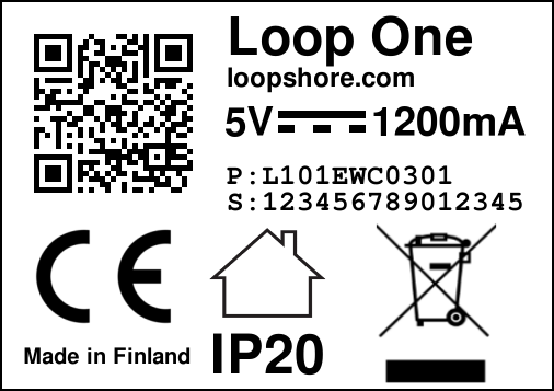
- The product’s serial number is marked with
S: serial_number. This serial number is also the device’s Device ID — the identifier shown in the Loopshore service and in notification emails. - The product’s product code is marked with
P: product_code
Interpreting the Product Code
XXXXXXXXXXX
XX--------- Product, LD=Loop Delta, L0=Loop Zero, L1=Loop One
--XX------- Version, e.g. 03
----X------ Approval, E = EU, P = Prototype
-----X----- Color, W = White, G = Grey, B = Black
------X---- Material, P = Plastic(ABS), C = Durasense(Biocomposite), 3 = 3D-printed
-------XX-- Battery, 02 = Li-Ion 1x4900mAh, 03 = Li-Ion 2x4900mAh
---------XX Lot, Lot identifier
Product Code Example
| Code | Description |
|---|---|
| LD03EWC0301 | Loop Delta, version 03, EU approved, white, Durasense biocomposite, 2×4900mAh battery, lot 01 |
Battery Wh
- 02 = Li-Ion 1x4900mAh / 17.78Wh
- 03 = Li-Ion 2x4900mAh / 35.56Wh
Technical Specifications
Table 1: Operating Conditions
| Parameter | Value |
|---|---|
| Temperature range | -20°C to +40°C |
| Humidity range | 0 to 100% |
Operating the device outside recommended conditions may affect the accuracy and lifetime of the device or specific sensors.
Table 1b: Sensor Operating Ranges
The operating ranges are those stated in the sensor manufacturers’ datasheets. The device operates outside these ranges, but the results of the affected measurement are not reliable. The sensor datasheets are listed in the Loopshore Sensors document.
| Measurement | Sensor | Operating range (manufacturer) | Notes |
|---|---|---|---|
| Temperature, humidity | Sensirion SHT45 | -40°C to +125°C, 0–100%RH | Humidity measurement is most accurate at +5°C to +60°C and 20–80%RH. Also operates in condensing conditions. |
| Differential pressure | Sensirion SDP8xx | -40°C to +85°C, non-condensing | Temperature compensation -20°C to +85°C. |
| Motion | ST LIS3DH | -40°C to +85°C | |
| Battery | Li-Ion | Operation -20°C to +60°C, charging 0°C to +45°C | Approximately 70% of rated capacity at -10°C. The device does not charge the battery below 0°C. |
Table 2: Device Specifications
| Parameter | Value |
|---|---|
| Size (WxHxD) | 96x132x35mm |
| Weight | 300g |
| Batteries | 1 or 2 pcs Li-Ion 3.63V / 4900mAh |
| Charging | 5VDC, USB-C |
| Microprocessor | ARM Cortex-M33 |
| Radio | NRF9160 |
| Frequency/Band | B1, B2, B3, B4, B5, B8, B12, B13, B14, B17, B18, B19, B20, B25, B26, B28 and B66 (700-2200 MHz) |
Measurement Ranges and Accuracy
Table 3: Differential Pressure
| Parameter | Value |
|---|---|
| Range | -125 to +125 Pa |
| Zero point accuracy | ±0.08 Pa |
| Span accuracy | ±3% of reading |
Table 4: Relative Humidity
| Parameter | Value |
|---|---|
| Range | 0 to 100% |
| Accuracy (typical) | ±2% |
| Accuracy (maximum) | ±3% |
Table 5: Temperature
| Parameter | Value |
|---|---|
| Range | -40°C to +85°C |
| Accuracy (typical) | ±0.2°C |
| Accuracy (maximum) | ±0.4°C |
Table 6: Motion
| Parameter | Value |
|---|---|
| Range | 0 to 16g |
| Accuracy | N/A |
Device Remote Monitoring and Operation
Note that the device includes Loopshore’s 24/7 remote monitoring and upgrade service. This means that Loopshore monitors that all devices are working correctly and takes action if deviations are detected. These actions may include, but are not limited to, software upgrades, configuration changes, default behavior changes, and customer communication.
If there are changes that affect this document, the document will be updated accordingly.
Appendices
Appendix 1 - Movement and Shock Detection
Loop Delta’s built-in movement and shock detection can be used to detect various things. These include:
- Whether the device has been moved.
- The device’s orientation in space.
- How much g-force is applied to the device and structures it is mounted on.*
For these acceleration measurements, the device continuously monitors its movement. If the device is moved even slightly, it starts precise acceleration detection for a few seconds. The maximum acceleration detected on each axis is then reported to the cloud service (in m/s²) along with other measurements. By default, the device can detect forces up to 8g and uses a 100Hz sampling interval.
Orientation-Specific Reports
If the device has not moved since the last measurement report was sent, its stationary orientation is measured and reported to the cloud service. After this report is sent, no acceleration data is reported until movement occurs again.
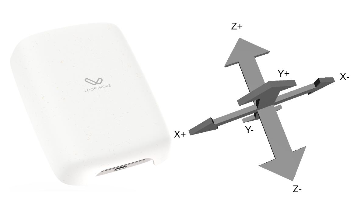
The acceleration report consists of 6 values. Each value represents the maximum acceleration detected for each direction. The picture below shows the direction of acceleration.
Example of Interpreting Raw Data
- Z- and Z+ are both 9.8m/s²
- Y- and Y+ are 0m/s²
- X- is -0.2m/s² and X+ is +0.2m/s²
This means the device is straight but upside down and shaking mildly sideways.
Shock Report
The device also reports the maximum g-force applied to it since the last measurement report was sent. If the device has not moved, this value is absent.
* Note that using only magnetic mounting will significantly affect measurement results. If accurate acceleration measurements are desired, glue and/or metal band fixing is recommended.
LOOPSHORE | Hämeenkatu 13 A 5, 33100 Tampere | info@loopshore.com | loopshore.com
© 2025 Loopshore