
Differential Pressure Sensor Installation
Installation Guide
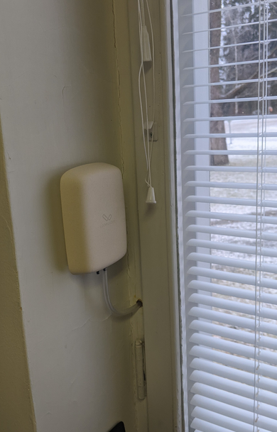
1. Drill a hole in the frame
Drill a 10 mm hole in the window frame using a wood drill bit. Make sure the drill bit is long enough for easy drilling. Blow out any drilling debris.
Pro tip: If you can angle the hole slightly outward, you can be sure that water won’t collect in the tube or flow in the wrong direction.
2. Thread the tube through the hole
Push the tube through the hole so that it extends a few centimeters outside the frame.
Turn the tube so that the end that was on the coil points slightly downward (not upward, so the tube doesn’t collect water).
We use 4/7 mm PVC tubing, which is available at regular hardware stores.
3. Seal the hole
Press the sealant nozzle alternately above and below the tube into the hole and squeeze sealant so that the space between the tube and the drilled hole is filled. This seals the opening and also protects the wooden frame structure from moisture.
Wipe off any excess sealant.
If possible, open the window and seal from the outside inward as well. Not essential for operation, but improves the end result.
4. Cut the tube and set it at a gentle downward slope
Position the sensor and tube so that the tube runs at a gentle downward slope toward the outside air along its entire length. This ensures that any water drains away and doesn’t pool in the tube – the same principle as in drains or drainage pipes.
Mark a suitable cutting point and cut the tube.
5. Attach the sensor
Attach the device by screwing the mount to the wall and placing the device on it.
Tip: You can also attach the wall mount using picture hanging strips (e.g. 3M Command strips, 12–20 mm wide) instead of screws. This requires no drilling and leaves no marks on the wall if the mount is later removed.
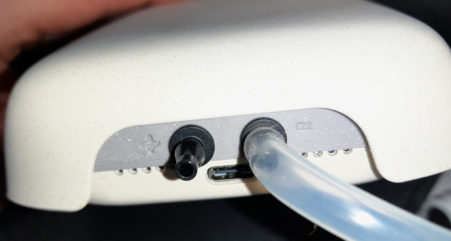
Connect the tube to the sensor’s minus port (–). You will see underpressure as negative values.
Usage and interpreting results
The differential pressure sensor measures the pressure difference between indoor and outdoor air in Pascals (Pa). The device has three measurement modes that can be adjusted from the Loopshore service.
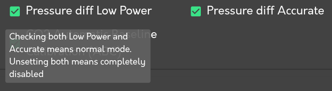
Measurement modes:
- Off – No measurements are taken.
- Low Power – Takes a single measurement at each measurement interval.
- Normal – Takes multiple measurements between measurement intervals. Reports minimum, maximum, and an outlier-filtered average. This is the default mode and is suitable for normal building monitoring.
- Accurate – Takes a large number of measurements (at least 100) between measurement intervals. Reports minimum, maximum, and an outlier-filtered average. Suitable for precise HVAC adjustment.
Interpreting results:
- Average (pressure_diff/Pressure difference): Smoothed average with outliers removed. Provides a stable, interference-free pressure reading.
- Minimum (pressure_diff_min/Minimum pressure difference): Lowest pressure reading detected during the measurement period. Useful for detecting pressure spikes (door openings, etc.).
- Maximum (pressure_diff_max/Maximum pressure difference): Highest pressure reading detected during the measurement period. Useful for detecting pressure spikes (door openings, etc.).
Configuring the measurement mode and free-flow setting
When commissioning a differential pressure sensor, the administrator configures two things from three device-configuration options — Pressure diff Low Power, Pressure diff Accurate and Pressure diff free flow.
Measurement mode is selected by the Pressure diff Low Power and Pressure diff Accurate options together (see the mode descriptions above for what each does):
| Pressure diff Low Power | Pressure diff Accurate | Mode |
|---|---|---|
| off | off | Off (measurement disabled) |
| on | off | Low Power |
| off | on | Accurate |
| on | on | Normal (default) |
Tubing type is selected by the Pressure diff free flow option, which must match the tubing. This is the single most important commissioning choice, because the wrong setting distorts the reading:
- Direct tube (PVC tube installation): leave “Pressure diff free flow” ON (the default).
- Capillary or thin copper tube: turn “Pressure diff free flow” OFF, which enables the capillary compensation algorithm (see below).
Measuring pressure difference with a capillary tube
The device also works with capillary tube installations. A capillary tube slightly reduces measurement accuracy compared to a direct tube installation, but a special compensation algorithm built into the device corrects most of the error.
We primarily recommend tube installation. Drilling and sealing the frame takes less than 5 minutes, and it saves you from maintenance visits every 1–3 months when a clogged capillary tube would need to be replaced.
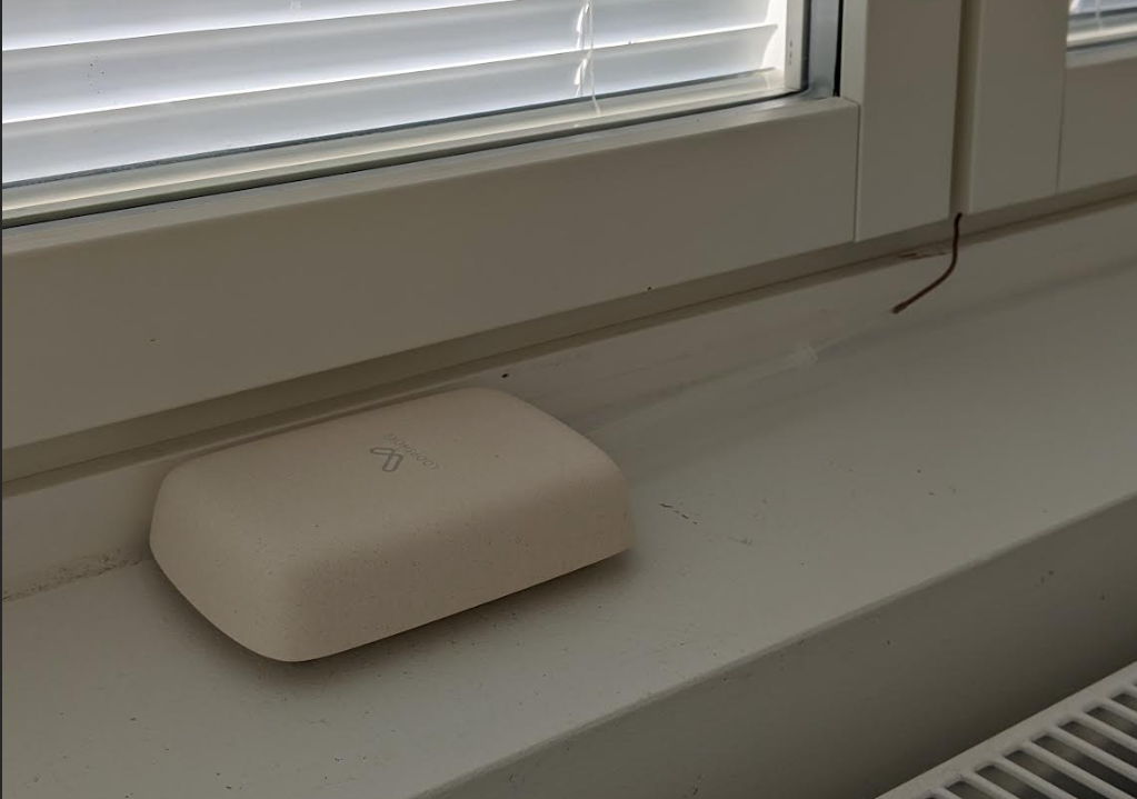
Installation through a seal without drilling:
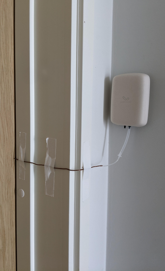
A working method is to use a tube from the Delta device that is routed through a window or door seal. This way, no drilling into structures is required. The actual tube is replaced at the structure with a thin copper tube, which is flexible and fits through the seal without being crushed. This way, the pressure outside the building envelope can be used as a reference pressure, and the device can reliably measure the pressure difference.
Capillary tube requirements:
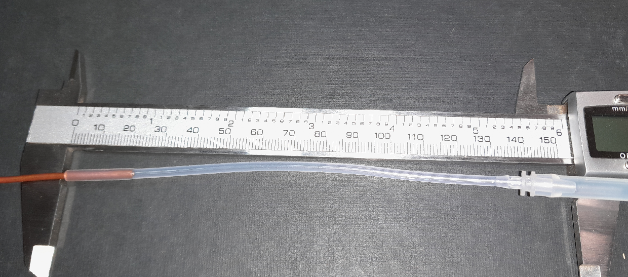
The compensation algorithm only works with the following dimensions: - Capillary tube: 400 mm long, inner diameter 0.8 mm - Connection tube: 150 mm long, installed 20 mm over the copper tube
Setting configuration:
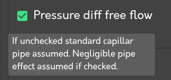
When using a capillary tube, uncheck the “Pressure diff free flow” setting in the Loopshore service. When this setting is off, the device uses the capillary tube compensation algorithm.
LOOPSHORE | Hämeenkatu 13 A 5, 33100 Tampere | info@loopshore.com | loopshore.com
© 2025 Loopshore